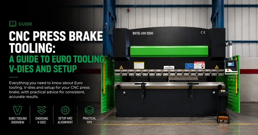
The tooling fitted to a press brake affects the parts you can make, the force each bend needs and the finish you achieve. A machine may have enough tonnage for the material, but the job still depends on choosing a suitable punch and die.
Confirm the punch and die fit the machine, then check the V opening, flange and load. Start with the tooling on Rhino torsion bar press brakes, and use the bending calculator for a first force and radius estimate.
For most workshops, the starting questions are straightforward. Will the tooling fit the machine? Which V opening suits the material and drawing? Is there enough clearance to complete every bend?
This guide explains Euro press brake tooling, how to approach V-die selection and what to check before production. For an initial estimate of bending force and geometry, use our press brake bending calculator.
What is Euro press brake tooling?
Euro tooling, also called European-style tooling, refers to a tooling mounting system. It does not describe one particular punch shape, V opening or bending capacity.
European-style tooling is available in different profiles and lengths, including traditional, fixed-height and staged systems. The word “Euro” alone is therefore not enough information to order a replacement tool. It describes the mounting style. It does not mean every European tool fits every machine.
Before buying additional tooling, confirm:
- The upper tool’s mounting profile and compatibility with the clamps.
- The lower tool’s fit with the die holder or bed arrangement.
- Tool height and the available working space.
- Punch profile, tip radius, die angle and V opening.
- Load ratings and any restrictions on short sections.
Ask for a tooling drawing and check it against the machine specification. A similar-looking tool is not proof of compatibility.
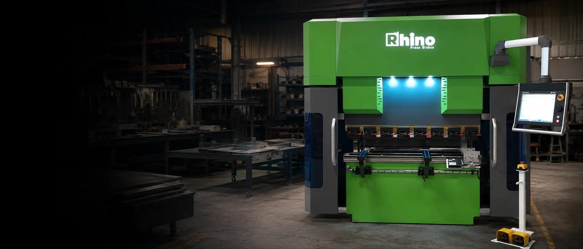
Our Rhino torsion bar press brakes are supplied with Euro-style tooling as standard. Discuss the actual punch and die package with us against your parts, particularly if you need short returns, enclosed shapes or specialist bends.
How the punch and V-die work together
The punch is the upper tool. The V-die is the lower tool that supports the sheet on either side of the bend.
In air bending, the punch presses the material into the opening without forcing it fully against the die faces. The penetration depth controls the bend angle, allowing a suitable tool combination to produce several angles.
Bottom bending and coining are different processes. Their tooling and force requirements must be assessed separately; an air-bending calculation should not be used to approve them.
This guide concentrates on air bending.
Choosing a V-die opening
For ordinary mild-steel sheet, a V opening around six to eight times the material thickness is a common starting point for air bending. It is a guide rather than a universal setting, especially as thickness, material strength and part requirements change.
The table below shows the arithmetic for an 8 × thickness starting point.
| Mild-steel sheet thickness | Calculated V opening at 8 × thickness |
|---|---|
| 1 mm | 8 mm |
| 1.5 mm | 12 mm |
| 2 mm | 16 mm |
| 2.5 mm | 20 mm |
| 3 mm | 24 mm |
These are planning examples, not a tooling selection chart. Confirm the available die sizes and the tool manufacturer’s recommendations.
What changes when you change the opening?
A narrower V generally produces a smaller natural inside radius and allows shorter flanges, but increases the bending force.
A wider V generally reduces force while producing a larger radius and requiring a longer flange. Changing the opening can also change the developed blank dimensions because the bend radius changes.
That is why choosing a larger die simply to reduce tonnage can create a different problem: the part may no longer match the drawing.
Check the required radius and shortest flange before settling on the opening.
Inside bend radius and minimum flange length
Two dimensions deserve particular attention when reviewing a part: the radius inside the bend and the length of the flange being formed.
The inside radius is not automatically the punch radius
During air bending, the sheet forms a natural radius influenced by the die opening and material. Fitting a punch with a 1 mm tip radius does not automatically produce a 1 mm inside radius.
Punch radius still matters. It must suit the material and bend; a tip that is too sharp can concentrate pressure and crease the sheet.
Short flanges need enough support
The sheet must remain supported by the die shoulders as the bend develops. Minimum flange length depends on the opening, shoulder geometry and bend angle.
Use the tool manufacturer’s dimensional convention when checking a drawing. An outside flange dimension and a straight length measured from the bend tangent are different measurements.
For a preliminary mild-steel calculation, our calculator estimates an inside radius of approximately 3.8 mm and a minimum flange/rest of approximately 16.8 mm with a 24 mm V opening. These are estimates to check against the actual tooling, not guaranteed finished dimensions.
If your drawing calls for a tighter radius or shorter flange, the tooling needs a closer review before the blanks are cut.
Choosing the punch profile
A punch needs to form the bend and leave room for the rest of the component.
| Punch profile | Typical reason to consider it | Main check |
|---|---|---|
| Straight punch | Simple bends with clear access | Clearance as the part moves through the bend |
| Gooseneck punch | Return flanges and shapes that would foul a straight punch | Throat clearance and the tool’s load rating |
| Acute-angle punch | Bends requiring a smaller included angle | Matching die geometry and springback allowance |
A gooseneck punch has a relieved profile that provides space for previously formed flanges. This can help with channels, trays and box work, but a deeper gooseneck can reduce load capacity compared with a straighter tool. Always use the rating for the specific profile.
Tool angles also need to allow for springback. A finished 90° bend may require the material to be bent beyond 90° while under load, so the punch and die must provide enough angular clearance.
Check the complete bending sequence. A tool may clear the first bend and obstruct the next one.
Segmented tooling and multi-V dies
Segmented tooling uses shorter sections that can be arranged to suit different bending lengths. This is useful when a full-length tool would interfere with an existing flange or restrict access to a component.
European tooling ranges include different height systems, so check working heights and alignment before combining sections. Sharing the same mounting style does not make every section suitable for use together.
A multi-V die provides several openings in one tool body. It can cover a useful range of work, but each opening still needs checking against the material, flange length and load.
When specifying a machine, ask which openings and tool lengths are included. “Tooling supplied” is only useful when the package covers the parts you intend to make.
Check tooling capacity as well as machine tonnage
Total machine force and tooling load are different checks.
Tooling is commonly rated in force per unit length, such as kN/m or tonnes-force per metre. A short bend can concentrate a substantial load into a small section of punch and die.
For example, 20 tonnes-force over a 200 mm bend equals 100 tonnes-force per metre. That is a load-intensity calculation, not permission to apply that force.
Check the punch, die, holders and clamping arrangement, including any manufacturer restrictions on short tool sections.
The machine also has limits on load distribution. Its headline tonnage does not mean that full force can be applied anywhere along the bed.
Our press brake tonnage guide explains the relationship between material strength, thickness, bend length and die opening.
Using the bending calculator to compare tooling choices
Our press brake bending calculator lets you enter the material, thickness, bend length, finished included angle and intended V opening.
Use it to compare estimated force, inside radius and minimum flange length before checking the proposed setup against manufacturer data.
For example, a 1,000 mm bend in 3 mm mild steel with a 24 mm V opening gives an estimated base force of approximately 24.4 tonnes-force, using the calculator’s assumed material strength. Any additional planning margin is separate from that base figure.
The calculation helps you assess a choice. It cannot confirm tool compatibility, collision clearance or whether a particular material batch will achieve the required result.
Planning the setup before production
A saved programme is most useful when it records the tooling and material conditions that produced the approved part. Material variation, springback and blank dimensions can all affect the result.
Use the following as a job-planning checklist alongside the machine’s operating instructions and operator training.
Start with the drawing. Record the material grade, thickness, bend angles, radii, flange dimensions and tolerances. Identify any dimension that leaves little room for adjustment.
Check the full sequence. Consider how each completed bend changes access for the next operation, including clearance around the punch, holders, machine and backgauge.
Confirm the tools. Record the punch and die references, working lengths and selected V opening. Check their condition, compatibility and rated limits before use.
Follow the approved setup procedure. Tool changes, alignment and safeguarding checks must follow the machine and tooling manufacturers’ instructions.
Prove the first part. Check the finished angle after springback, flange dimensions, radius and surface finish. Where relevant, measure at several points along the bend.
Save the proven information. Keep the tool references, material details and approved corrections with the job. Recheck the first part when the job returns rather than assuming a stored programme removes the need for inspection.
Specifying tooling for a new press brake
When choosing a press brake, bring examples of your regular work. A few representative drawings tell us more than a maximum sheet thickness alone.
Useful details include:
- Material grades and thicknesses.
- Longest bend and shortest flange.
- Required inside radii.
- Return bends, channels or box sections.
- Surface-finish requirements.
- Typical batch sizes and frequency of changeovers.
Our Rhino torsion bar press brake range includes Euro tooling, with installation and operator training from Mantech. We can discuss the supplied tooling and any additional requirements against the work you plan to produce.
Need help matching the machine and tooling to your parts?
Send us your drawings, material details and bending lengths, or call 0121 541 1444. For sites in Ireland, call (+353) 83 804 8820. We’ll help you assess the requirements before you choose a press brake.
Discuss your press brake requirements
Useful next reads
- Rhino torsion bar press brakes
Euro tooling on the torsion bar range, including the tooling band.
- Press brake bending calculator
Estimate air-bending force, inside radius and minimum flange for a chosen V opening.
- Press brake tonnage guide
How material, thickness, bend length and die opening change the force.
- How to choose a CNC press brake
Bed length, control class and installation once the tooling fit is clear.
- Rhino Premium CNC press brakes
Multi-axis CNC bending when the torsion bar range is not the fit.